40 wiring battery isolator diagram
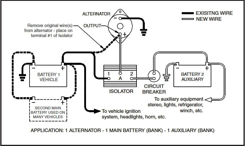
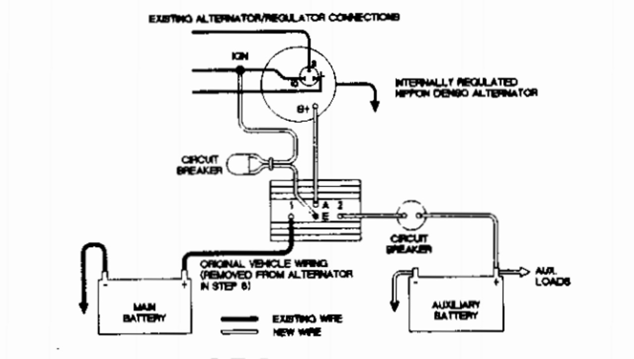
The QuadBoss Battery Isolator might seem small, but the impact it could have on your rides is massive. We take you step-by-step through the installation proc... I've found a wiring diagram for the # DW08771 Battery Isolator. Terminal 1 would connect to the positive battery terminal of the main battery. The original wire from the alternator to the main battery would be removed from the battery and installed on terminal 1.
Rv Battery isolator Wiring Diagram. rv camper trailer battery isolation app notes application notes for battery isolation with the hellroaring battery isolator biners for multi battery dual battery auxiliary battery deep cycle and upeor high current battery disconnect isolator cut off buy upeor high current battery disconnect isolator cut off switch for car marine boat rv atv vehicles ...

Wiring battery isolator diagram
There are two things that will be present in any Rv Battery Isolator Wiring Diagram. The first component is symbol that indicate electric component from the circuit. A circuit is usually composed by various components. Another thing which you will get a circuit diagram would be lines. Wiring Diagram. The installation of a multi-battery isolator is quite simple as long as you carefully . Install hardware to the studs in the order shown in diagram, being careful not.The NOCO High-Performance Battery Isolator is a solid-state electrical device, which eliminates multiple battery drain and prolongs battery life. We offer design, installation, service, and support for marine electronics and ... I recently watched your video on how to install battery isolators ...
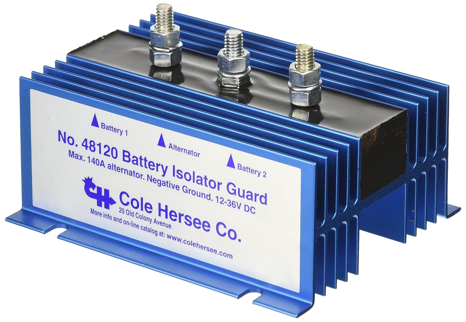
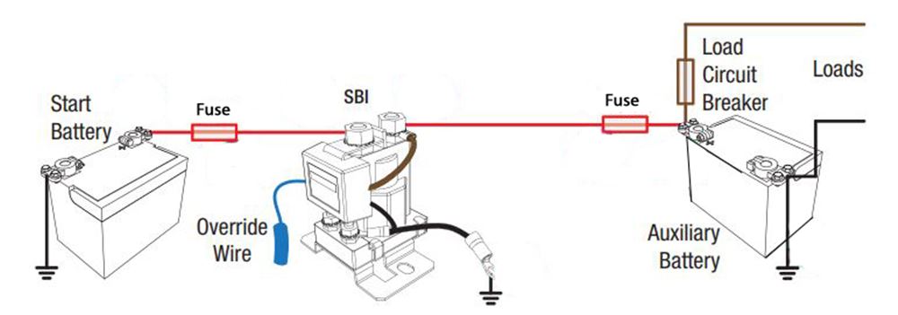
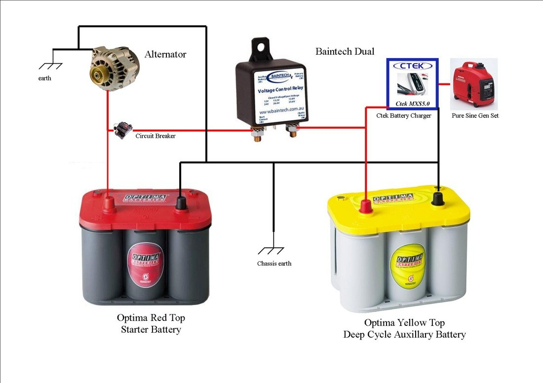
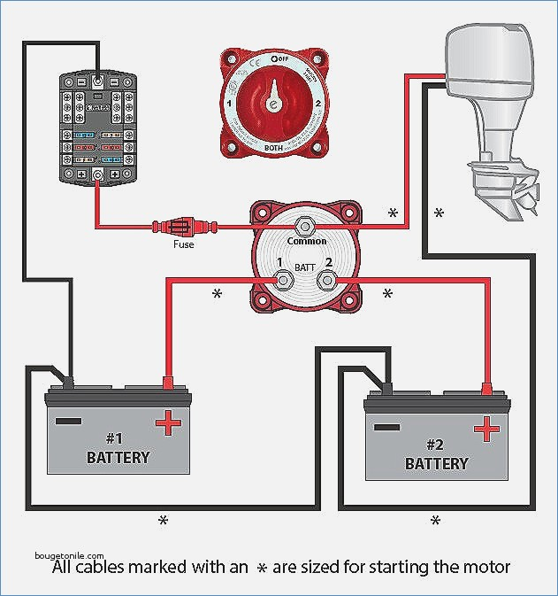
Wiring battery isolator diagram. Here is a diagram of a typical installation. The following picture shows the actual unit installed in a boat. The single post in the middle secures the wire from the alternator. The other two wires run to the starter battery and the deep cycle battery positive post respectively. Bussmann RB-BI-70A 70 Amp Battery Isolator We are an Amazon Affiliate. A. You can charge the auxiliary battery with a battery charger without affecting the battery isolator at any time. When charging the starting battery the isolator will automatically connect the auxiliary battery when the starting battery reaches 13.4V (about 75% charged) and will then be charged also. This is not an ideal way to fully charge ... The Li-BIM is a Battery Isolator specifically designed to work with Lithium house batteries. Lithium batteries like Battle Born batteries have a slightly higher resting voltage than their AGM or Lead Acid counterparts. The standard AGM tuned isolator will see this higher voltage as a 'charging' voltage and will not disconnect the starting and house batteries which means the starting ... Wiring Diagrams. Please choose a year from the menu at left to start your search.
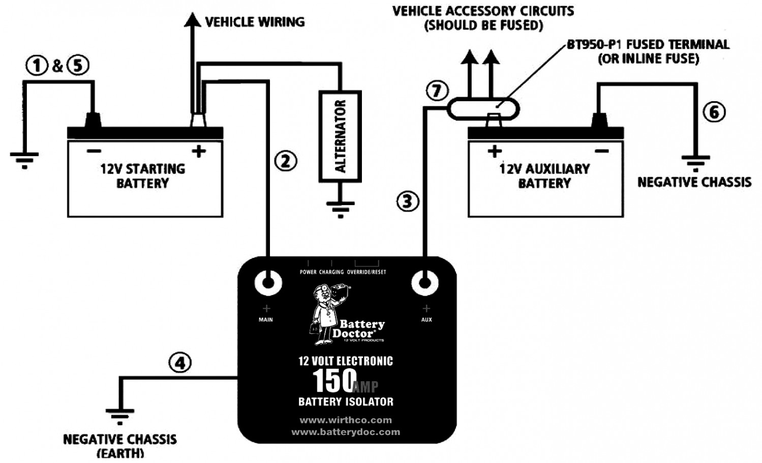
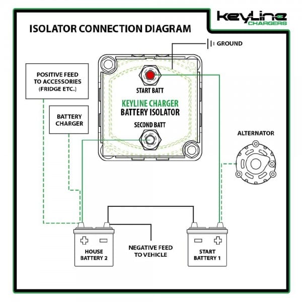
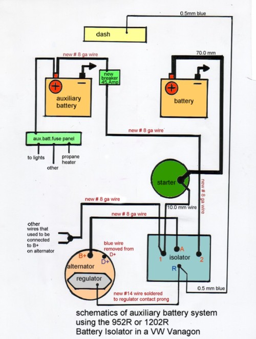
battery 6. Mount a circuit breaker as near to the auxiliary battery as practical, and away from engine or exhaust heat (see application chart for proper size). Connect one end of a new wire ensuring it is the correct size to the "2" terminal of the Isolator. Run the wire to the circuit breaker and connect it to the "AUX" terminal. 4. Install a new wire from the alternator output post to the "A" terminal of the isolator. 5. Install a new wire from "B1" terminal of isolator to main engine battery. 6. Install a new wire from the "B2" terminal of isolator to auxiliary battery. 7. On a 3 -battery system con nect a new wire from "B3" to second auxiliary battery. 8. Step by step Battery Isolator install (12V 140 Amp Dual Battery Isolator by KeyLine Chargers - Voltage Sensitive Relay (VSR) Pro Dual Battery Kit). This isol... A battery isolator only transfers power from the alternator to a secondary battery. The van's alternator is designed to keep a float charge (13.8V) on a starter battery as well as provide enough power to keep all of the van's equipment running, such as lights and a stereo.
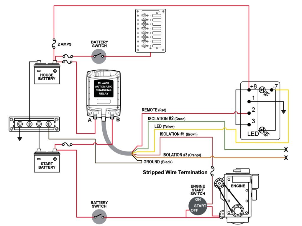
Wiring a Battery Isolator Written by Heather Domabyl on Dec 08, 2010. To ensure our content is always up-to-date with current information, best practices, and professional advice, articles are routinely reviewed by industry experts with years of hands-on experience. Reviewed by . H.R. Helm. on Jan 03, 2020. 1-3 hours ... See the table that follows for the recommended wire size and circuit breaker for your installation. For optimum system performance it is recommended that a ...4 pages Battery Isolator Wiring Diagram? - We're finishing up a party bus with a sound system and led lighting, etc. in the back. I need to charge the main bus batteries (2) and a deep cycle in the rear from the bus alternators or from a gas powered 12vdc generator I put together with a honda motor and an a Wiring Diagram Wiring the relay: 1. The black wire coiled inside the relay needs terminated to a good ground location using the included blue crimp connector. This wire is simply used as a ground for activating the relay. 2. One terminal on the relay should be connected to the positive terminal of the primary starting battery using 6ga red wire.
Cole Hersee Battery isolator Wiring Diagram | Free Wiring ...
The Battery Isolator must be fully connected before starting the engine. If the engine kill output signal is not connected when the engine is running then damage to the Battery Isolator may occur. (Cars without alternators do not apply). Do not use the Internal Button for any other application, it is designed specifically for use with Battery ...
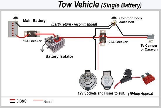
Caravan & Camper Battery Charging @ ExplorOz Articles
Maxresdefault With Dual Battery Isolator Wiring Diagram For At 7 - Dual Battery Isolator Wiring Diagram. Wiring Diagram contains many detailed illustrations that display the link of various items. It consists of directions and diagrams for different types of wiring strategies as well as other things like lights, windows, and so forth.

Stinger Battery isolator Wiring Diagram | Free Wiring Diagram
Battery isolator Wiring Schematic. Assortment of battery isolator wiring schematic. A wiring diagram is a streamlined conventional pictorial representation of an electric circuit. It shows the components of the circuit as simplified shapes, as well as the power as well as signal connections between the devices. A wiring diagram typically offers details about the…

32 Rv Battery Isolator Wiring Diagram - Wiring Diagram List
Wiring Instructions. 1. Remove Earth from main battery and mount the isolator ( with the red and black wires the auxiliary battery. 6. Ensure that the second battery is correctly earthed to motor and body. Wiring Diagram for DBES MKIII.Jan 09, · Simple Dual Battery Wiring Diagram and Parts List - DIY for $ This is a simple system that will ...

On my first trip to SF I was in a conference mostly, but I had a chance to check out the sunrise one day. As we took a Lyft from the hotel to Battery Spencer the fog was so bad that you couldn’t even tell you were on the bridge; even when we were dropped off at the parking lot you couldn’t see anything. The short walk from the parking lot to the viewpoint put me above the clouds and I was blessed with the most amazing view of Golden Gate I could imagine. As the sun rose the fog would hide and reveal the bridge in the most amazing ways. I took so many good photos of this, more in profile.
Jun 8, 2017 - dual alternator battery isolator wiring diagram.
Dual batteries???? - Ford Truck Enthusiasts Forums
Wiring diagram for Battery Isolator. Question: Not sure what post 1-2-A-and E go to. asked by: Mike. 1. Helpful Expert Reply: For your battery isolator similar to # DW08771, you will have connection posts for each battery and for an alternator. The main battery will connect to position one and the alternator to the A post.

Stinger Battery Isolator Wiring Diagram - Free Wiring Diagram
Dual Battery Isolator Schematic. After answering numerous questions about different battery isolator schemes, I decided it would be easier to just build a webpage. Below you will find the basic design of 3 types of battery isolators with the pros and cons of each.
Dual Battery Wiring And Isolation Using 7622 - Toyota Fj ...
As stated previous, the traces in a Dual Battery Isolator Wiring Diagram signifies wires. At times, the cables will cross. But, it doesn't imply connection between the cables. Injunction of 2 wires is generally indicated by black dot at the intersection of two lines. There will be primary lines which are represented by L1, L2, L3, and so on.
Wiring Diagram for Deka 95-amp Battery Isolator # DW08770 ...
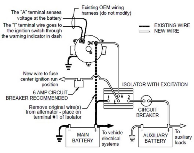
A group 3 isolator will have a colored fourth terminal indicating the "R" terminal. When in doubt of alternator type, call Sure Power Industries with alternator make and model number. If application is a Dodge Sprinter using the Bosch alternator, a battery isolator is not compatible. Use of a Battery Separator is recommended (verify
Multi Battery Isolator Wiring Diagram
2. Replace rubber plug in the alternator -The other end of the yellow wire can now be connected to isolator terminal Battery #1 or directly to the main battery as shown in the installation diagram. Option: A slot can be cut half way through the plug, making sure the plug covers the yellow wire. 3.

Stinger Battery isolator Wiring Diagram | Free Wiring Diagram
Disconnect Both Batteries - Install the isolator on a panel as close as possible ... to the second battery as shown in the installation diagram - Use wire.4 pages
TheSamba.com :: Gallery - Noco battery isolator wiring diagram
Topic: Car Audio Wiring How to Wire a Battery Isolator . Connecting multiple batteries can intimidate the do it your self installer, however the process is fairly simple when broken down. No matter how many batteries your adding each one of them needs to be isolated. ... Below is a diagram that shows the process.

Boat Battery Isolator Switch Wiring Diagram - Wiring ...
Canadian Energy™ - Battery Isolator : 101 - Youtube - 12V Battery Isolator Wiring Diagram Wiring Diagram includes numerous comprehensive illustrations that display the link of assorted things. It consists of instructions and diagrams for various varieties of wiring techniques along with other things like lights, windows, and so forth.

Boat Dual Battery Wiring Diagram For Yanmar Sel - Wiring ...
True Battery isolator Wiring Diagram Collection. true battery isolator wiring diagram - What's Wiring Diagram? A wiring diagram is a type of schematic which uses abstract photographic signs to show all the interconnections of components in a system. Electrical wiring diagrams are made up of two points: icons that stand for the parts in the circuit,…

BillaVista's Dual battery setup
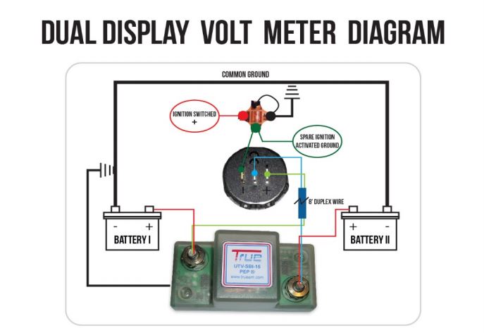
DUAL DISPLAY VOLT METER DIAGRAM COMMON GROUND BATTERY I SPARE 8' WIRE BATTERY Il DIRECTION FOR WIRING ON/OFF RELAY VOLT METER Note: These directions apply to the round and the rectangular, dual display, ... One end to either side of isolator and the other end, J one to each silver blade on meter. (Top blade is top meter).

Sure Power Battery isolator Wiring Diagram Download
We offer design, installation, service, and support for marine electronics and ... I recently watched your video on how to install battery isolators ...
Redarc Smart Start Battery Isolator - 12 Volt - 200 Amp ...
Wiring Diagram. The installation of a multi-battery isolator is quite simple as long as you carefully . Install hardware to the studs in the order shown in diagram, being careful not.The NOCO High-Performance Battery Isolator is a solid-state electrical device, which eliminates multiple battery drain and prolongs battery life.
12V Battery Isolator Wiring Diagram | Wiring Diagram
There are two things that will be present in any Rv Battery Isolator Wiring Diagram. The first component is symbol that indicate electric component from the circuit. A circuit is usually composed by various components. Another thing which you will get a circuit diagram would be lines.

Battery isolator Wiring Schematic | Free Wiring Diagram

150 Amp Battery Isolator

Battery Combiner Wiring Diagram - General Wiring Diagram

Sure Power Battery isolator Wiring Diagram Collection

Windows in clouds, clouds in windows - instagram.com/pwellgraf
Dual Battery Isolator Wiring Diagram - Wiring Diagram

the pride of san francisco, golden gate bridge

View of New Jersey from Battery Park

Motorhome Battery Isolator Wiring Diagram

Kawasaki ZX1000A Ninja 1985 - 1987 USA Colour Wiring Diagram

Battery isolator Wiring Schematic | Free Wiring Diagram

Battery sharing is growing steadily and fast. No time to charge your Battery? Shove it into the Swobbee charger and exchange your Kumpan Electric battery for a full one. As simple as that.💚

Image result for rv battery isolator wiring diagram | rv ...

Cole Hersee Smart Battery Isolator Wiring Diagram

Battery Isolator Diode Schematic
Marine Battery Isolator Wiring Diagram
How To Wire A Battery Isolator Diagram - General Wiring ...
Battery Isolator
Help wiring isolator 9523a on 1985 Sunrader - Electrical ...
12v dual battery isolator wiring diagram car boat marine

Sure Power Battery isolator Wiring Diagram Download

Battery Isolator Wiring Diagram - Wiring Diagram And ...
0 Response to "40 wiring battery isolator diagram"
Post a Comment