40 honeywell hz221 wiring diagram
03.10.2019 ... Can someone confirm if the Honeywell HZ221 control panel is ... Mine is wired to the battery that powers my electric gate which has a solar ... For assistance with this product please visit http://honeywellhome.com ... The following diagram is an overall view of wiring for a heat pump system as ...8 pages
23.01.2015 ... Honeywell Thermostat Hz221 Users Manual 69 2200 01 TrueZONE ... L M28236A R C M28237 The following diagram is an overall view of wiring for ...

Honeywell hz221 wiring diagram
The Honeywell RTH111 comes with a jumper wire installed between the Rh and Rc terminals. These supply power to the heating and cooling systems respectively. If you have only one power wire (which is usually red), leave the jumper in place and connect the wire to either Rc or Rh. However, if you have separate Rc and Rh wires, remove the jumper ... The illuminated emergency heat light indicator means that your Honeywell thermostat EM heat is switched on. And, your HVAC system is currently relying only on your auxiliary heating unit. If you didn't activate the emergency mode, first confirm to ensure that someone else hasn't activated it, either by mistake or on purpose. If it was by ... 1. Verify that the wiring was matched correctly from the old thermostat to the new thermostat. If there are not separate wires to R and Rc, these terminals must be connected. On some thermostats this connection is made by a jumper wire connection and on other models this connection is made by a slider switch that has 1-wire and 2-wire settings.
Honeywell hz221 wiring diagram. Honeywell HZ221 WiriNg . WiriNg, 69-22000 , 69-22000, The following diagram is an overall view of wiring for a heat pump system as depicted in steps 37. 23.10.2021 ... No wiring necessary. Discharge Air Temperature Sensor (DATS):. Sensor which protects HVAC equipment. Divide the Home Into Zones There ... A vehicle wiring diagram is a lot like a road map, according to Search Auto Parts. Wiring diagrams are laid out similar to a road map because the diagrams show how each major electrical system, individual circuit and sub-system connects, th... or call Honeywell Zoning Hotline toll-free at 1-800-828-8367 ... The following diagram is an overall view of wiring for a heat pump system as depicted in ...8 pages
Followed the Honeywell wiring diagram that applied to my situation exactly and it worked like a charm. Only unexpected thing was that I was expecting the valves ... Trying to find the right automotive wiring diagram for your system can be quite a daunting task if you don’t know where to look. Luckily, there are some places that may have just what you need. Here’s where to start. Before you search for a... ZONE 1 THERMOSTAT ZONE 2 THERMOSTAT ZONE 3 THERMOSTAT DAMPER DAMPER DAMPER HZ432 TrueZONE HEa T p u Mp Use the following diagram for wiring a 3-heat/2-cool heat pump with electric stage 3 heat. Honeywell CPRD8 8-Inch Truezone Bypass Damper 4. I'm going with the Honeywell TrueZone Zone control system and their ZD dampers. Height adjustment. For assistance with this product please visit http://honeywellhome.com ... The following diagram is an overall view of wiring for a heat pump system as ...8 pages
Honeywell TrueZone Panel Installationhttp://www.CleanAirSystemsInc.net. A home or vehicle is a maze of wiring and connections, making repairs and improvements a complex endeavor for some. Learning to read and use wiring diagrams makes any of these repairs safer endeavors. These simple visual representations all... In some cases, one of those wires may be your common. If you have a C wire, place it into the C terminal on your wall plate. Let's take a look at the G wire. This wire will go to the G terminal on your new thermostat. For the Y, Y1, and Y2 wires, Y or Y1 will go to the Y terminal, and Y2 will go to the Y2 terminal. View online (16 pages) or download PDF (6 MB) Honeywell Home HZ221, HZ221K Installation ... Use the following wiring diagrams to wire the zone panel to the ...
Pin on Zone Controls
HZ221 TrueZONEWiringWiring must comply with applicable codes, ordinances, ... following diagram is an overall view of wiring for a heat pump system as ...

RHEEM Gas furnace Honeywell controller C wire question ...
About Honeywell Ecobee Hz311 . Product Description. Use any thermostats - nest, ecobee, honeywell, etc. Read honest and unbiased product reviews from our users. Get special offers & fast delivery options with every purchase on Ubuy; the leading international shopping platform in Australia. Red/R* - power wire for your heating and cooling system.
HZ221K - Honeywell HZ221K - TrueZONE Kit with DATS ...
HZ22 TrueZONE WiriNg Wiring must comply with applicable codes, ordinances, and regulations. CAUTION: Voltage Hazard. Can cause electrical shock or equipment ...

Honeywell TrueZONE 4-Zone 3H/2C Control Panel Kit | 24V ...
s For deviations to these wiring diagrams or the job specific wiring diagrams, consult the factory. Wiring-Wiring 2 TR21-A sensors. Sep 07, 2021 · Honeywell Home T9 Wifi Smart Thermostat Rcht9510wfw2001 W Honeywell Store from www. Jason D'Aprile / IDG. The Ecobee 4 is intuitive in its design and functionality, and easy to install.

ZoningSupply.com - Zone Control - SmartZone-4X
Logic diagram., minuend which is complemented before applied at the AND gate to implement the borrow output. 2b) Give the unminimized sum-of-products expression. gate2: or. Logic diagram. This online program generates the simplified function based on the input and output values of a function using Karnaugh Maps method.

Honeywell CM737 Thermostat Operation & user's manual PDF ...
1. Verify that the wiring was matched correctly from the old thermostat to the new thermostat. If there are not separate wires to R and Rc, these terminals must be connected. On some thermostats this connection is made by a jumper wire connection and on other models this connection is made by a slider switch that has 1-wire and 2-wire settings.

Goodman GMT Blower Runs Intermittently - HVAC - DIY ...
The illuminated emergency heat light indicator means that your Honeywell thermostat EM heat is switched on. And, your HVAC system is currently relying only on your auxiliary heating unit. If you didn't activate the emergency mode, first confirm to ensure that someone else hasn't activated it, either by mistake or on purpose. If it was by ...

I have an issue with my Honeywell Mini Zone EMM3 unit. I ...
The Honeywell RTH111 comes with a jumper wire installed between the Rh and Rc terminals. These supply power to the heating and cooling systems respectively. If you have only one power wire (which is usually red), leave the jumper in place and connect the wire to either Rc or Rh. However, if you have separate Rc and Rh wires, remove the jumper ...

QTY KT8900 UHF/VHF repeater system - YouTube

HZ221 : Honeywell TrueZONE Single Stage, 2 Zone Zoning ...

Wiring-HZ221 TrueZONE, wiring

Closeup of skeleton pelvic model

I am trying to install a Honeywell RTH8500 Programmable ...

Wiring help needed for a 1-phase 220v reversing puzzle ...

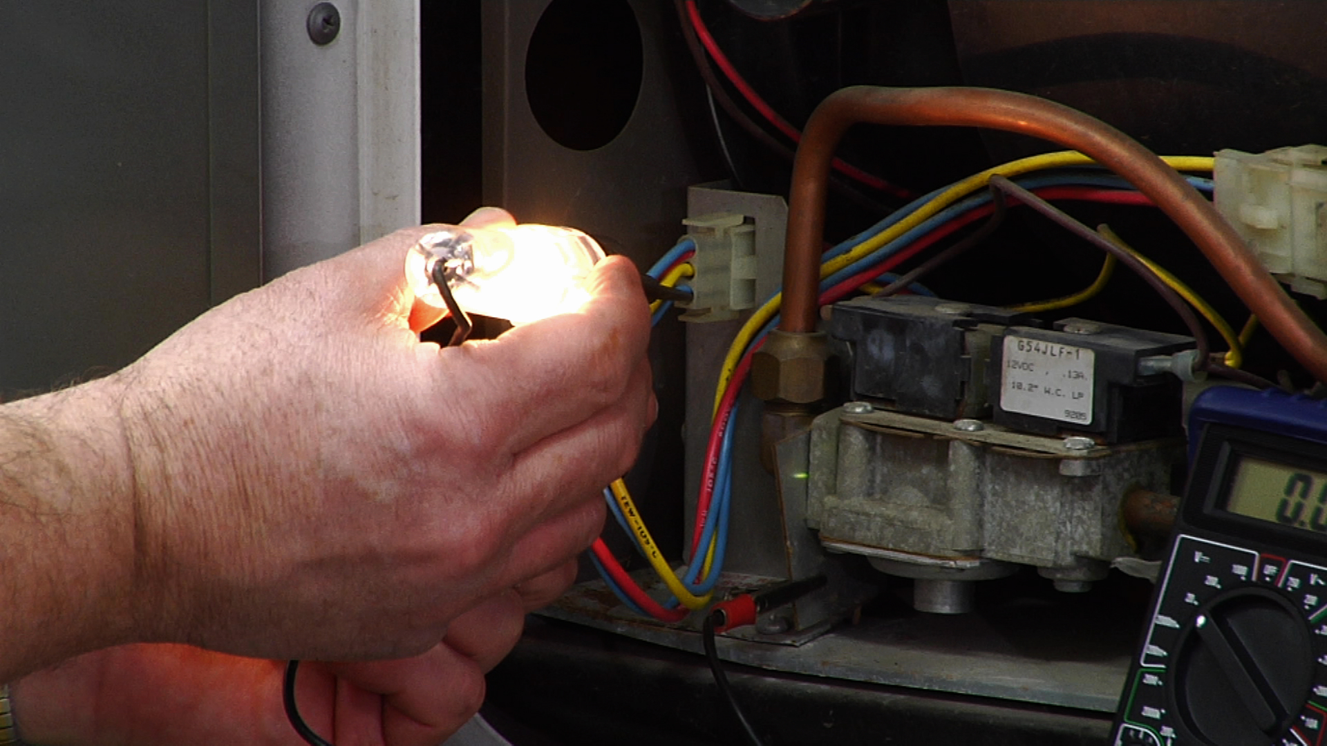
Honeywell HE360 not working--connected to Goodman GMV95 ...

My heater is taking forever to heat up. Cool is working ...
Wiring Thermostat Honeywell 8320U to Furnace-heat pump ...

Wiring for for Honeywell Thermostat - DoItYourself.com ...

Nest with Honeywell HZ311 : Nest
Wireless Replacement for Drayton RTE thermostat | DIYnot ...

Closeup of skeleton hand model

6 Year Old Water Heater has reset switch trip every few ...

Honeywell S8910U1000 - Ignition Module
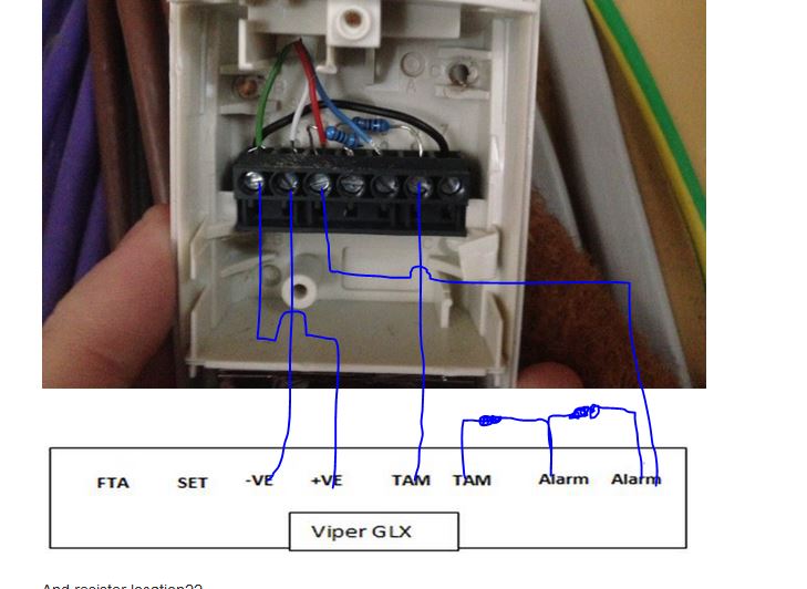
Switching Pir To Viper Glx Shock - Wiring Advice - Galaxy ...

HONEYWELL HZ221K TRUEZONE CONTROL PANEL FOR HEAT PUMP ...

Honeywell UDC3200 Universal Digital Controller

Closeup of skeleton hand model
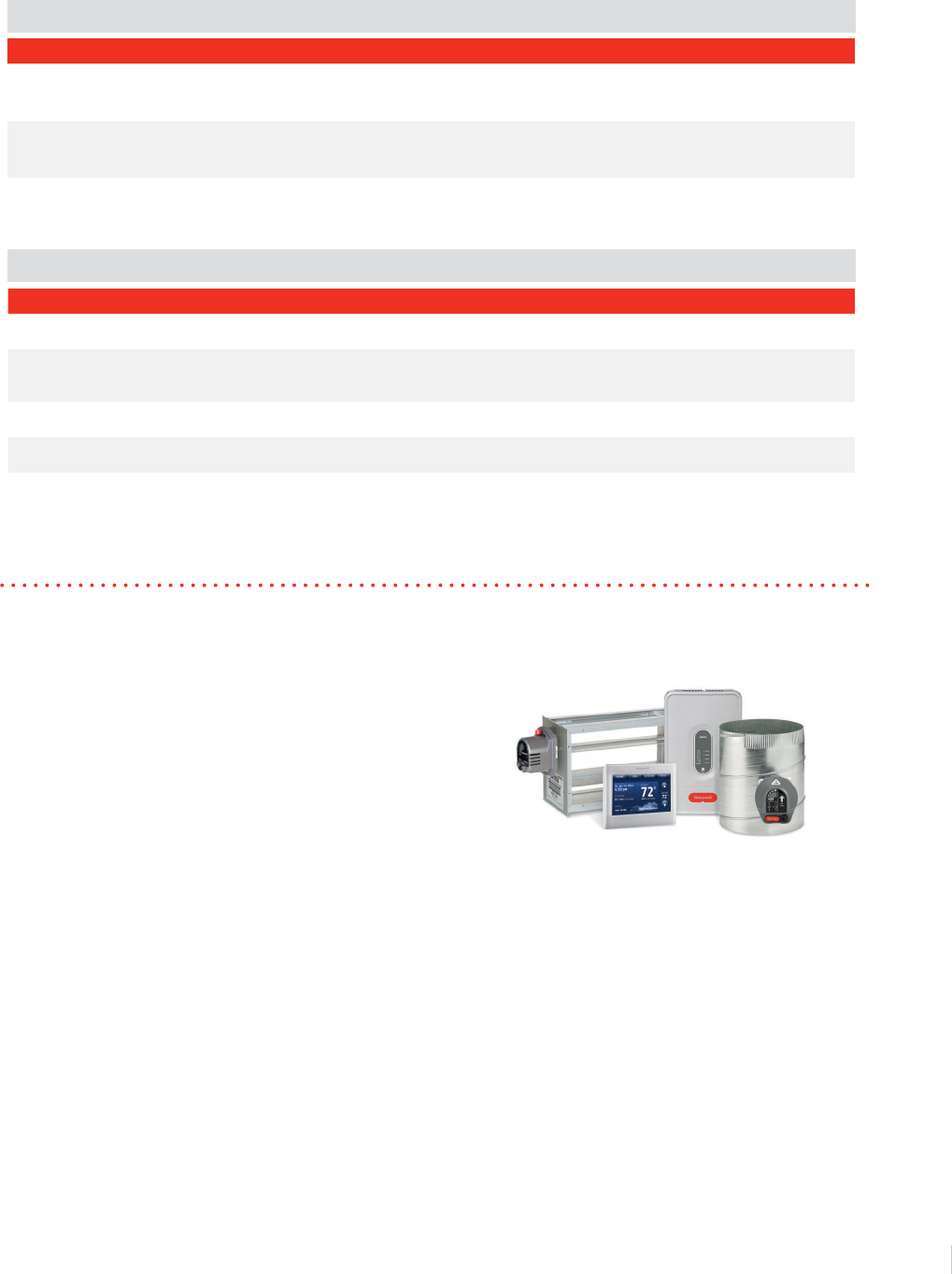
Zoning Product Family Brochure Honeywell Thermostat HZ221 ...

Wiring-Overall wirring of heat pump system
Boiler heating not firing up when Drayton SCR green light ...

TrueZONE® Kit | Honeywell Home

hvac - Honeywell Zone System Wiring - Home Improvement ...

TrueZONE® HZ221 Panel | Honeywell Home
Hive and Potterton Titanium | DIYnot Forums

Honeywell Zone Board Wiring Diagram - Wiring Diagram
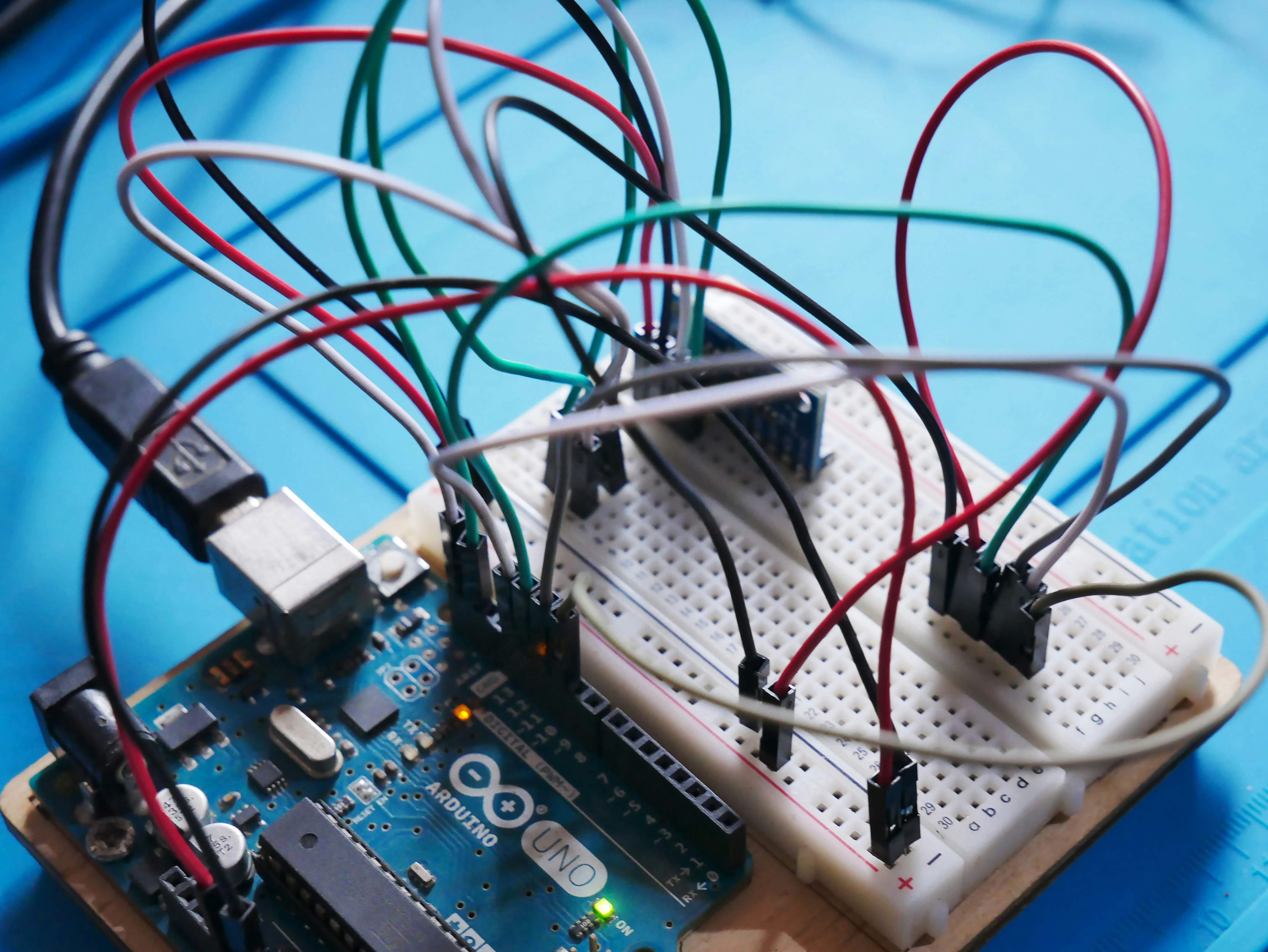
An Arduino Uno board wired to a couple of sensors on a breadboard.

Programmable Thermostat Lux Products TX1500E - YouTube
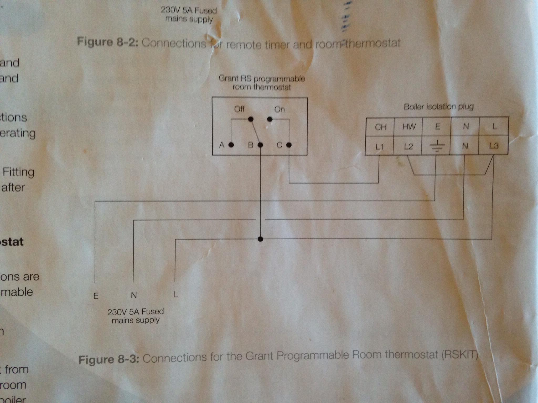
Grant Vortex Combi & Honeywell BDR91 Thermostat | DIYnot ...
RV Furnace Troubleshooting Methods

New member needs help !! - DoItYourself.com Community Forums
0 Response to "40 honeywell hz221 wiring diagram"
Post a Comment