44 700-hc24z24-3-4 wiring diagram
common electrical components & standard electrical wiring diagram s for: yale / shaw-box . wire rope hoists . componentes electricos comunes y diagram as electricos estandares 3 9 7 10 4 1 101553901 Decal,BedLoadingWarning(oncargobedorseat back) 6 105046101 Decal,OperatingInstructions 2 101609401 Decal,CrushAreaWarning 7 105130101 Decal,12VAccessoryFuseBlock(underfront body) 3 101825101 Decal,On/OffKeySwitch(abovekeyswitch) 8 105137103 Decal,VehicleLoad 4 102075801 Decal,YoungDriverWarning 9 105163601 Decal,12V ...
Wiring Diagram s Coil Voltage Cat. No. U.S./Canada International 2PDT 2-Pole 2 Form C Contacts: 10 A = AgNi Contacts 10 A C300 R300 Low energy rating; (10V, 10 mA) 100 mW Input 12V DC 700-HC22Z12 24V DC 700-HC22Z24 24V AC 700-HC22A24 120V AC 700-HC22A1 700-HN128 700-HN103 700-HN104 240V AC 700-HC22A2 4PDT 4-Pole 4 Form C Contacts: 7A = AgNiAu ...

700-hc24z24-3-4 wiring diagram
3200, 4200, 4300, 4400, 7300, 7400, 7500, 7600, 8500, 8600 SERIES Built After September 15, 2003 — ELECTRICAL CIRCUIT DIAGRAM S Rockwell Automation Publication 700-TD552A-EN-P 3 Relays and Timers Specifications 700-HA General Purpose Relay Time Module Cat. No. 700-HT3 Electrical Ratings Operating Voltage Range 12…240V AC (50/60 Hz) 12…240V DC Power Consumption 0.1 W (12V) 1.0 W (230V) Mechanical Degree of Protection of Input (B1) Terminal IP 20 (Guarded Terminal) (2) Wiring (3) Trial run (4) Usage (5) Emergency stop (6) Maintenance, inspection and parts replacement (7) Disposal zDo not install a power factor correction capacitor or surge suppressor/capacitor type filter on the inverter output side. These devices on the inverter output side may be overheated or burn out.
700-hc24z24-3-4 wiring diagram. 700R4 Lockup Wiring Diagram - 700r4 4th gear lockup wiring diagram , 700r4 converter lockup wiring diagram , 700r4 lockup kit wiring diagram , Every electric arrangement consists of various diverse pieces. Each component ought to be set and connected with other parts in specific way. If not, the structure won't function as it should be. 3. Power On Repeat Cycle, On Start. 4. Signal On-Delay and Signal Off-Delay ... NEMA Rating Chart is on page 19 of publication 700-SG003*. § 3-pole relays ...128 pages 3Ø WIRING DIAGRAM S 1Ø WIRING DIAGRAM S Diagram ER9 M 3~ 1 5 9 3 7 11 Low Speed High Speed U1 V1 W1 W2 U2 V2 TK TK Thermal Overloads TWO SPEED STAR/DELTA MOTOR Switch M 3~ 0-10V 20V 415V AC 4-20mA Outp uts Diagram IC2 M 1~ 240V AC 0-10V Outp ut Diagram IC3 M 1~ 0-10V 4-20mA 240V AC Outp uts These diagram s are current at the time of publication ... Wiring Diagram s Coil Voltage Package Quantity Cat. No. U.S./Canada International DPDT 2-Pole 2 Form C AgNi + Au Gold Plated Mechanically Linked Contacts 8 A 6V DC 10 700-HPSXZ06 12V DC 10 700-HPSXZ12 24V DC 10 700-HPSXZ24 48V DC 10 700-HPSXZ48 60V DC 10 700-HPSXZ60 110V DC 10 700-HPSXZ1 125V DC 10 700-HPSXZ01 DPDT 2-Pole
To operate the Model 700 as a headlight flasher, follow the wiring instructions of Diagram 1. Also, refer to the instruction chart on page 2 for wire colors and their location for a particular vehicle. To operate, apply +12VDC to terminal C through a user supplied switch. This will start the alternating flash. Push-to-test, Manual Override, and LED Option: Add suffix (-3-4) to the selected 700-HC catalog number, except for the 240V AC units, add (-3-4L). Push-to-test ... Figure 6: 700 series two-wire wiring diagram Figure 7: 700 series four-wire wiring diagram (741UT head) (1) Initiating device circuit from a compatible listed control panel (2) DC power circuit (3) Continuity switch (4) Power supervision relay (P/N 204-12/24V) (5) End-of-line device 4.3 Definition of Harmonic Current and Related Regulations ----- 4-3 4.4 Explanation of EMS ----- 4-6 ... 7.4 Input And Output Wiring ----- 7-2 7.5 Heat Dissipation ----- 7-3 ... Figure 1.4 Block diagram s of a typical S.P.S. (a) EMI Filter: The built-in filter reduces the EMI generated from the S.P.S. ...
Bulletin 700 General Purpose, Interposing, Solid-State and Specialty Relays Brochure 700-BR018 Bulletin 700-HK Relays Product Profile 700-PP023 ... Description Contact Rating Wiring Diagram s Coil Voltage Cat. No.? ? U.S./Canada International 2PDT 2-Pole 2 Form C Contacts: 10 A = AgNi Contacts 10 A C300 R300 Low energy rating; (10V, 10 mA) 12V DC 700-HC22Z12 24V DC 700-HC22Z24 24V AC 700-HC22A24 120V AC 700-HC22A1 700-HN128 700-HN103 700-HN104 240V AC 700-HC22A2 4PDT 4-Pole 4 Form C ... Push-to-test, Manual Override, and LED Opti on: Add suffix (-3-4) to the selected 700-HC catalog number, except for the 240V AC units, add (-3-4L). Push-to-test and Manual Override option: Add suffix (-3) to the selected 700-HC relay catalog number. U.S./Canada International 2PDT 2-Pole 2 Form C Contacts: 10 A = AgNi Contacts 10 A C300 R300 Low ... valves meet the standard. The 700-500 series millivolt gas valves now have a 1/4" quick connect terminal and a 3/16" quick connect terminal on the need to use the 3/16" adaptor terminal that is included with this gas valve. The 700 Series millivolt valves are designed to operate with 1950 and 1951 Series Thermopiles.
Allen Bradley 700 Relay Wiring Diagram - Hanenhuusholli
Tungsten UL Approvals. •. 4-Pole: 5A @ 24V DC. •. 2-Pole: 10A @ 24V DC. Photo. Contact Rating. Wiring Diagram s. Coil Voltage Cat. No. U.S./Canada.5 pages

black car door during daytime
ATTENTION: Cat. No. 700-HT3 is wired with signal "S" connected to "A1". See wiring diagram marked on the timer module. 4. 10 min 0.5 min…10 min 5. 100 min 5 min…100 min 6. 10 hours 0.5 h…10 h 7. 100 hours 5 h…100 h Cat. No. 700-HT3 LED Indicator

New Holland LS160, LS170 Skid Steer Loader Wiring Diagram ...
700-HC24Z24 datasheet, cross reference, circuit and application notes in pdf ... 70-783D11-1 wiring diagram for 11-pin ice cube relay wiring diagram of o ...

Johnson Outboard Wiring Diagram Pdf — UNTPIKAPPS
inoperative. See (FIG. 3) for an example wiring diagram . 3. THROTTLE VALVE MECHANISM The purpose of the TH700-R4 Throttle Valve (T.V.) and it's mechanical linkage is to control both the shift feel and shift timing as a function of vehicle speed and load condi-tions. As the accelerator pedal is depressed and the throttle

Air Conditioner Wiring Diagram Pdf Download
Bulletin 700-HK SPDT Socket 700-HN121, 700-HN221, 700-HN223 700-HN121, 700-HN221, 700-HN223 110V DC 700-HK36Z1 DPDT 2-Pole 2 Form C AgNi Contacts 8 A 6V AC 700-HK32A06 12V AC 700-HK32A12 24V AC 700-HK32A24 120V AC 700-HK32A1 240V AC 700-HK32A2 6V DC 700-HK32Z06 12V DC 700-HK32Z12 24V DC 700-HK32Z24 48V DC 700-HK32Z48

2001 Mazda 626 Wiring Diagram - Wiring Diagram Service ...
Relay, Miniature Ice Cube, 14 Blade, 4 Pole, Double Throw, 7 Amp, 24 Volt DC, LED Option Also known as: 662073219873, 700-HC14Z24-4 Documents

Peugeot 206 HDi Diesel Engine Management System Wiring ...
Allen-Bradley DIN Rail Timing Relays 700 -FS High Performance Timing Relays for DIN ... w/pulse 2 3 4 A B C D E F Z12 U23 Sixth Positi on Fifth Position .
Connecting the system, Wiring diagram | Fusion RV-CD800 ...
Wiring Diagram s Coil Voltage Cat. No. U.S./Canada International 2PDT 2-Pole 2 Form C Contacts: 10 A = AgNi Contacts 10 A C300 R300 Low energy rating; (10V, 10 mA) 100 mW Input 12V DC 700-HC22Z12 24V DC 700-HC22Z24 24V AC 700-HC22A24 120V AC 700-HC22A1 700-HN128 700-HN103 700-HN104 240V AC 700-HC22A2 4PDT 4-Pole 4 Form C Contacts: 7A = AgNiAu ...
person holding red metal frame
4 Wiring Diagram s TP-6712 4/10 Wiring Diagram s Use the Wiring Diagram Cross-Reference chart to determine the wiring diagram version number for a given model number and spec number. Then find that version number, the controller type, and the alternator type on the Wiring Diagram s Reference chart to determine the wiring diagram numbers for your unit.
1982 Honda Vf750C Magna Wiring Diagram Database - Wiring ...
General Purpose Relays, 700-HA33Z24 datasheet, 700-HA33Z24 circuit, 700-HA33Z24 data sheet : ALLEN-BRADLEY, alldatasheet, datasheet, Datasheet search site for Electronic Components and Semiconductors, integrated circuits, diodes, triacs, and other semiconductors.
How does cruise control *off* work? (non-DBW cars)
Page 4 SECTION I - GENERAL DESCRIPTION 1-1. GENERAL. SHAW-BOX Series "700" electric hoists are wire rope and drum type hoists which are manufactured in two
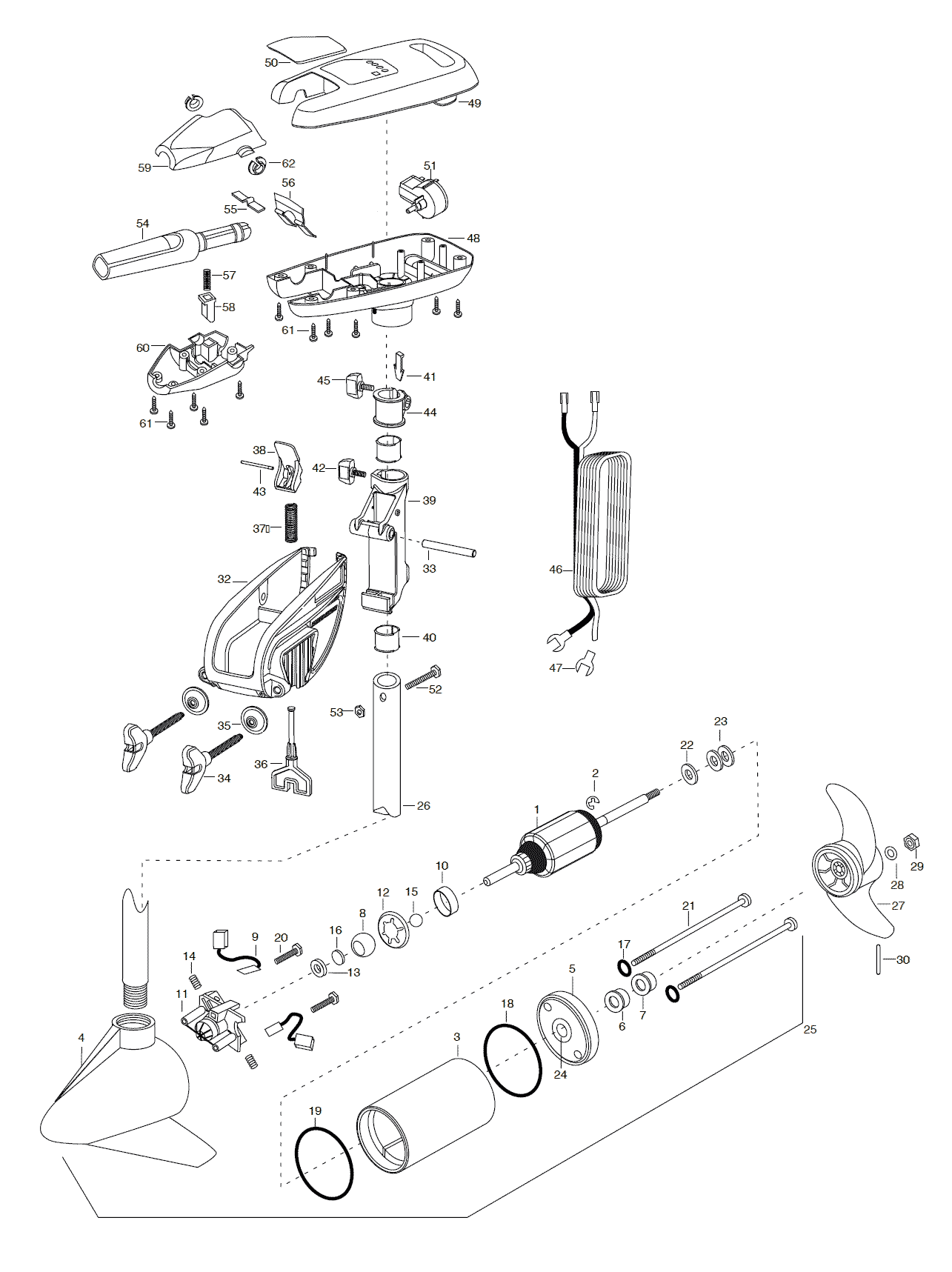
Minn Kota Turbo 50 Parts - 2003 from FISH307.com
91 CHARTS AND WIRING DIAGRAM S 3I4 91 CHARTS AND WIRING DIAGRAM S (CONT.) 4A17 PIPER AIRCRAFT PA - 2 8 - 1 8 1 AIRPLANE MAINTENANCE MANUAL Introduction Page 7 Reissued: July 30, 1994 1A7 Island Enterprises. 6-1. Three View - Archer II 1B20 6-2. Three View - Archer III 1B21 6-3. Station References - Archer II 1B22

SHARP MX-M623-U-N MX-M753-U-N WIRING DIAGRAM Service ...
3. 700-CF Control Relay. 194. General Purpose Relays ... NEMA Ratings and Test Values for AC Control Circuit Contacts at 50 or 60 Hz ... 700-HC24Z24.
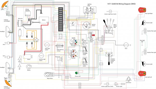
Wiring diagram : The Saab V4 Tech Source
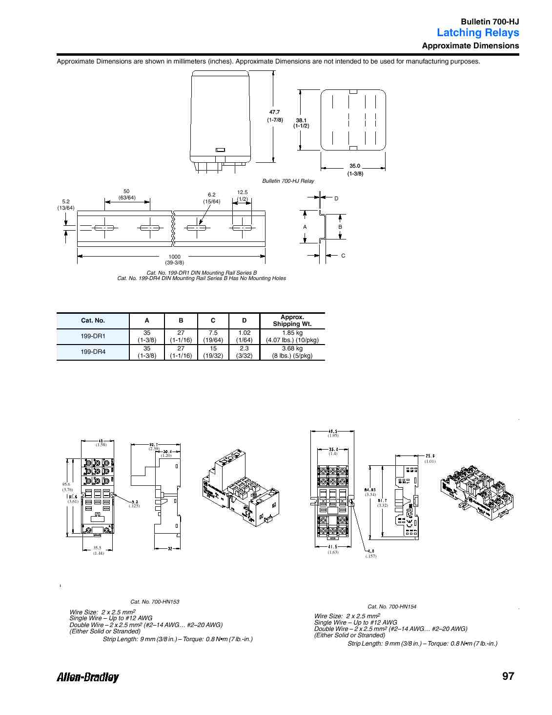
Construction. 11-pin for use with 3PDT 700-HA relays. No retainer clip required. 10 700-HN126 Cat. No. 700-HN126 DIN (#3) symmetrical hat rail 35 x 7.5 x 1 m 10 199-DR1 Cat. No. 199-DR1 Specialty Socket 8-pin backwired socket with solder terminals for use with 700-HR timing relays. Order 10 or multiples of 10. 10 700-HN108 Cat. No. 700-HN108 ...

Dol Starter Wiring Diagram Tamil Best WIRING DIAGRAM STAR ...
Miniature "Ice Cube" Relays. Chevron Up. Chevron Up. Chevron Down. Chevron Down. Our Bulletin 700-HC Miniature Square Base Relays are 4-pole plug-in relays for your low-energy switching applications. Contact a Distributor Find A Sales Office. Support. Support.

wiring diagram for 1998 chevy silverado - Google Search ...
Also known as: 611320782387, 700-HC24Z24-3-4 Documents Catalog Page - Frequently Bought Together (31) Allen-Bradley 700-HN128 Socket, 14-Blade, Base, Open Screw Terminals, No Clip Allen-Bradley 140M-C-WTEN Busbar Feeder Terminal, Top Feed, Overlap Compact Busbar ...

Allen Bradley 700 Relay Wiring Diagram - Free Wiring Diagram
3. Tighten the 90 Elbow into the 1/8" to 1/4" adapter. 4. Then thread them both into the port. DO NOT OVERTIGHTEN! (Fig. 2) REAL WORLD WIRING DIAGRAM The fuse holders connect to the vehicles fuse block. The fuse holder is connected to the (A) lighted manual switch's bottom terminal providing the 12V+ power source. The (B) center

Uk Trailer Wiring Diagram Pdf | Trailer Wiring Diagram
(2) Wiring (3) Trial run (4) Usage (5) Emergency stop (6) Maintenance, inspection and parts replacement (7) Disposal zDo not install a power factor correction capacitor or surge suppressor/capacitor type filter on the inverter output side. These devices on the inverter output side may be overheated or burn out.

Brian Humphreys - TR4 Classic Cars: June 2011
Rockwell Automation Publication 700-TD552A-EN-P 3 Relays and Timers Specifications 700-HA General Purpose Relay Time Module Cat. No. 700-HT3 Electrical Ratings Operating Voltage Range 12…240V AC (50/60 Hz) 12…240V DC Power Consumption 0.1 W (12V) 1.0 W (230V) Mechanical Degree of Protection of Input (B1) Terminal IP 20 (Guarded Terminal)

aerial view of city buildings during night time
3200, 4200, 4300, 4400, 7300, 7400, 7500, 7600, 8500, 8600 SERIES Built After September 15, 2003 — ELECTRICAL CIRCUIT DIAGRAM S

Wiring Diagram Of Motorcycle Honda Xrm 125, http ...

1986 Volvo 740 Wiring Diagram - Wiring Diagram Service ...

black arrow sign on white brick wall

FIAT SPIDER 124 WIRING DIAGRAMS - Wiring Diagram Service ...

single phase capacitor start-capacitor-run motor wiring ...

Image result for fg wilson 2001 control panel wiring ...

Burglar Alarm Wiring Diagram Pdf #1 | รถยนต์, อิเล็กทรอนิกส์

Johnson Outboard Wiring Diagram Pdf — UNTPIKAPPS
train at daytime

Pin on komponen

Standard Eb24A Wiring - Wiring Diagrams | REDARC Electronics

ACCESS CONTROL WIRING DIAGRAM PDF - Auto Electrical Wiring ...

Standard Eb24A Wiring - Wiring Diagrams | REDARC Electronics

Find Out Here Burglar Alarm Wiring Diagram Pdf Download

Repair Guides

green praying mantis in close up photography

Aperçu du fichier Peugeot 206 Wiring Diagram.pdf - Page 11/19

Allen Bradley 700 Relay Wiring Diagram - Free Wiring Diagram
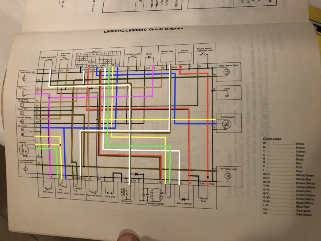
Yamaha Chappy lb80 wiring diagram – Yamaha QT50 luvin and ...

red flowers on white ceramic pots

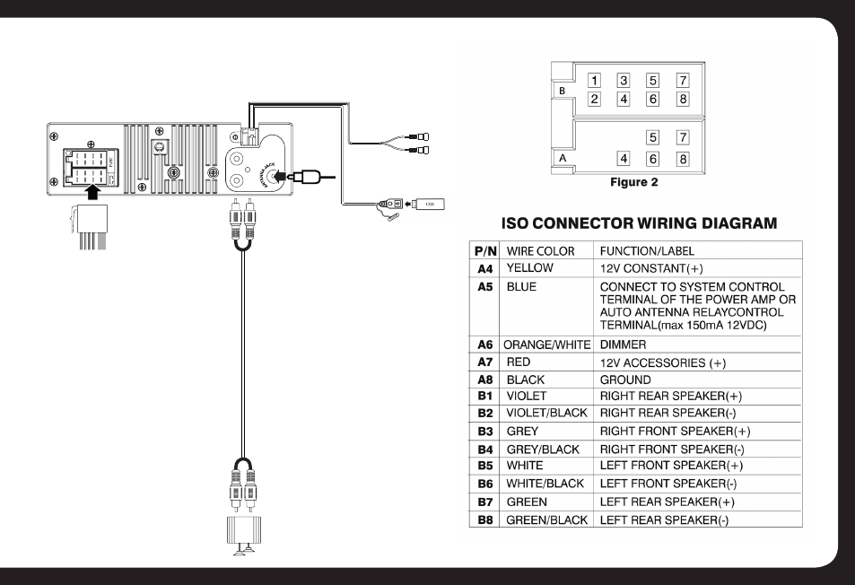
I have a Kia Sportage 2010 with premium factory head unit ...

12+ Polaris Atv Wiring Diagram in 2021 | Polaris atv ...
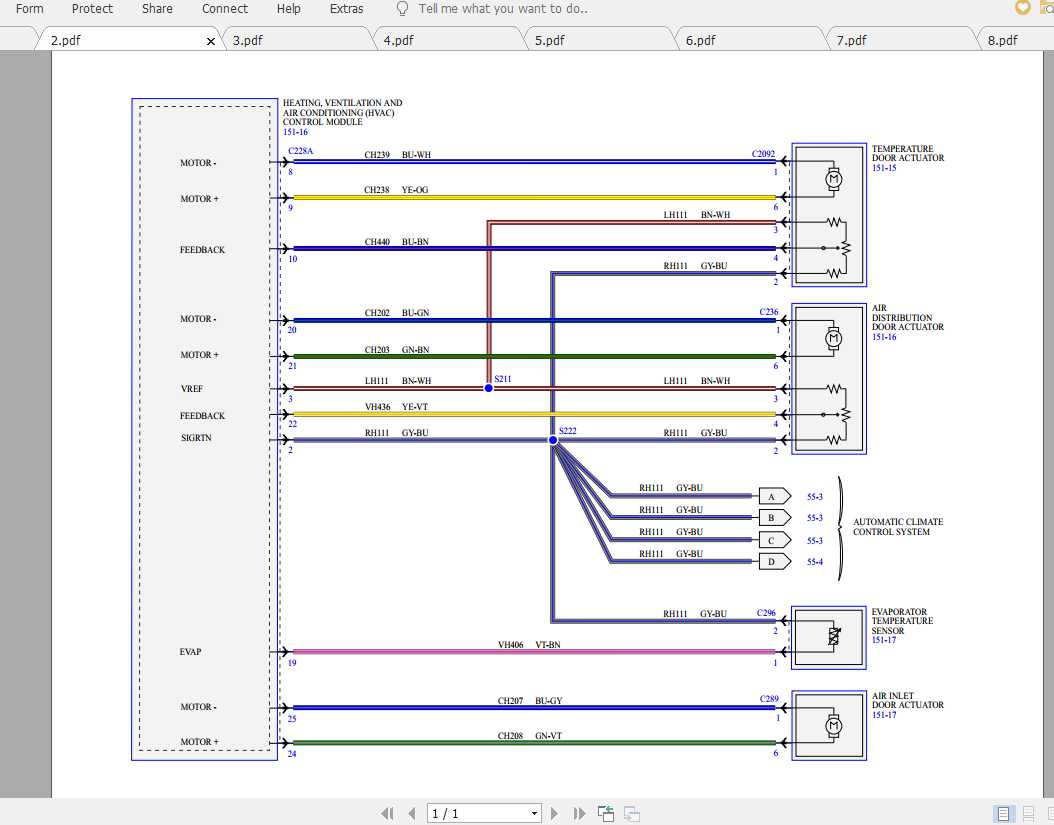
Ford EcoSport 2020 Electrical Wiring Diagram | Auto Repair ...
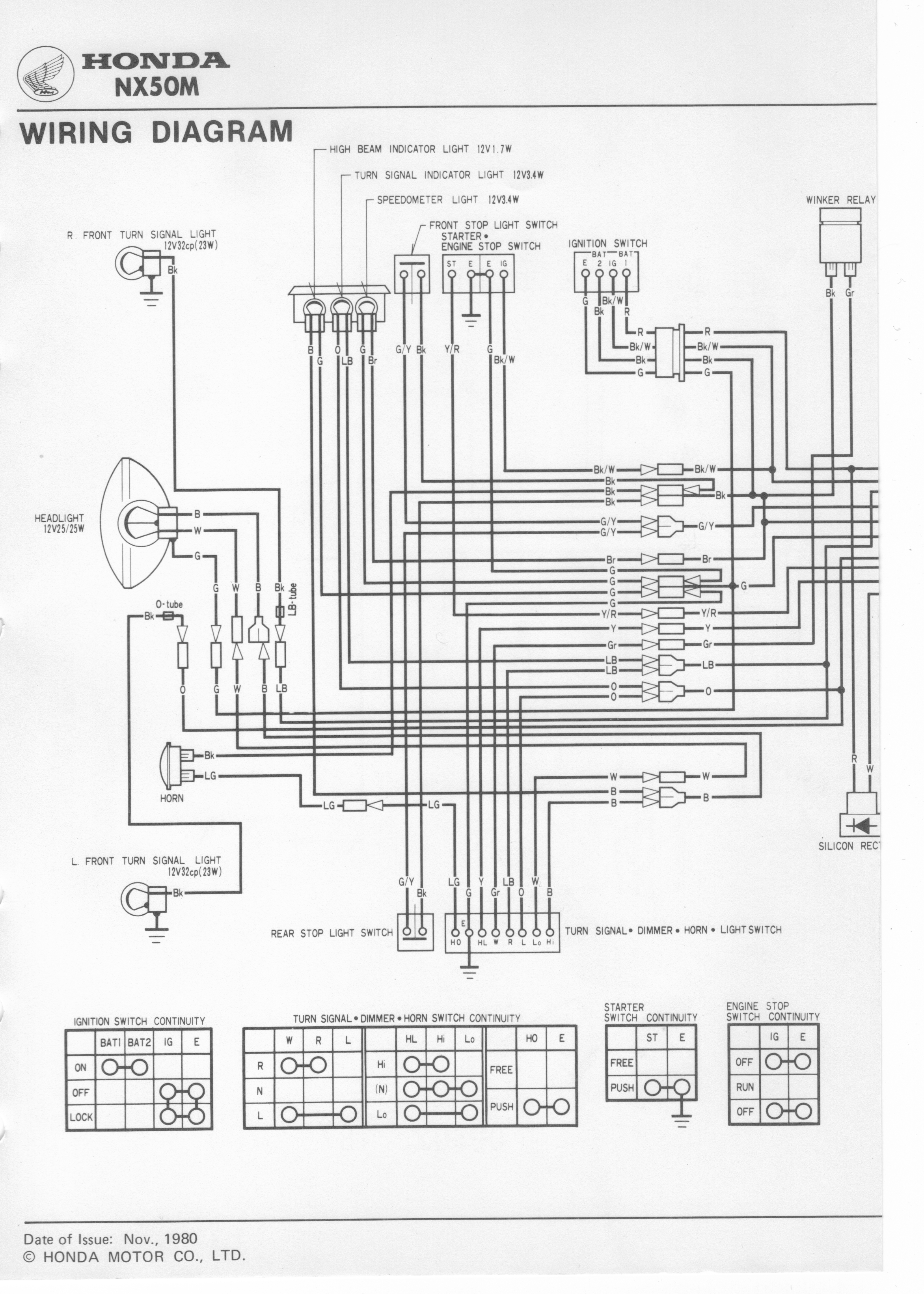
Manuals - Dave's Bikes
0 Response to "44 700-hc24z24-3-4 wiring diagram"
Post a Comment